Jump to content


U-Sump filter construction


  • Please log in to reply
15 replies to this topic

#1 Guest_mywan_*

Guest_mywan_*
  • Guests

Posted 21 April 2011 - 09:39 AM

Here are the basic parts for the portable PVC u-joint sump filter or U-Sump. More pictures will be added as construction continues.
Posted Image
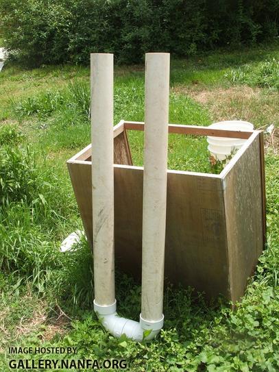
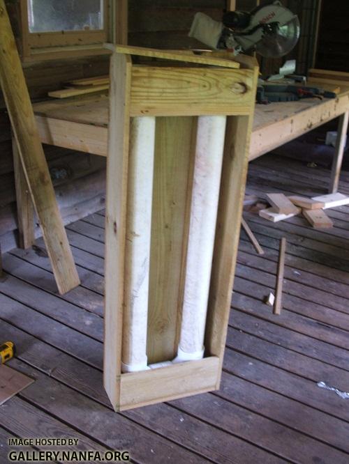
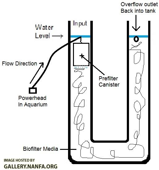
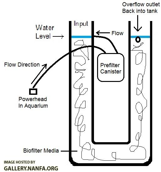
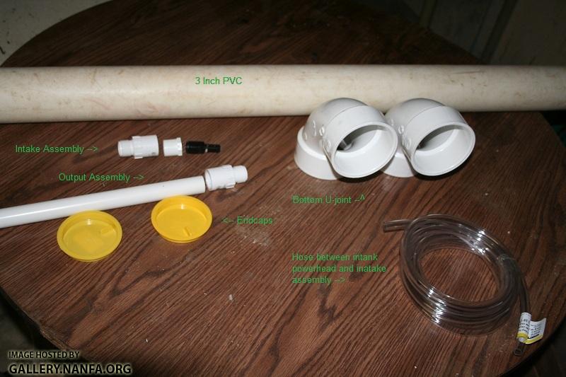
(Clog bypass not included in pic - thanks gerald)

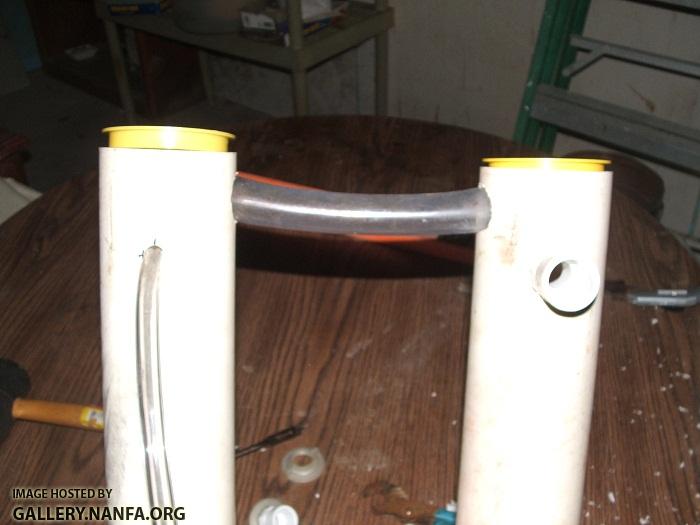
The above picture uses 3" inch PVC with an expected water level 44 inches from the floor, or bottom of the sump. This provides a total sump volume of 2.7 gallons. This could be greatly increased with larger diameter PVC. Here is the volume tables.

Volume Table (same height 44"):
3" inch PVC = ~2.7 gallons
4" inch PVC = ~4.8 gallons
6" inch PVC = ~10.8 gallons
8" inch PVC = ~19 gallons

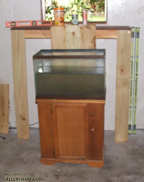
I am using 3" inch PVC as a demonstration because I had some extra 3" inch PVC pipe laying around and it should be big enough for the 20 gallon tank I will test it on.

Objectives:
1} Provide a large volume small footprint sump pump that can be placed behind any standard aquarium on a standard 29 inch base, or on a platform for higher tanks.
2} Remove any need for special plumbing not self contained in the sump and kept at a bare minimum making it highly portable between tanks and locations.
3} Provide the overflow on the return side to avoid the loss of priming of the siphon on standard tanks lacking a built in overflow.
4} Reduce the head pressure on the pump to near zero to maximize flow rates from any given pump.
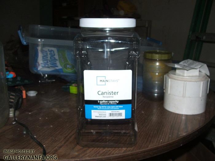
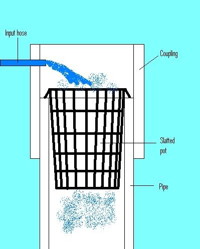
5} Provide easy access and maintenance of the primary filter without requiring the pump to be shut down.
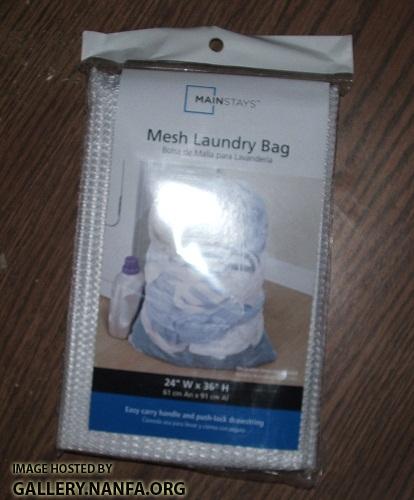
6} Provide a range of filtration media options easily accessible and maintainable.
7} Increase the number of bioballs or equivalent the water column must pass through in the sump.
8} Provide an external self contained location to include heaters, aerators, etc.

Caveats:
Because the water is pumped from the tank and gravity feed back in it will not maintain a constant water level as the water evaporates, but a minimum level can be maintained by limiting the depth of the pump. If it sucks air it is time to add water. If a tank has a built in overflow, or it is simply preferred, you can overflow into the U-Sump and place the pump inside the return pipe rather than the aquarium. Without a built in overflow that does not require a siphon that would require the water level in the U-Sump to be somewhat below tank level. This makes me think I should make it reversible in this way up front.

Many more features will be added later. Looks like I need to get out the chop saw because I can not find a tiny piece of my hacksaw that holds the blade on.

#2 Guest_mywan_*

Guest_mywan_*
  • Guests

Posted 21 April 2011 - 12:59 PM

The basic U connections should be straightforward. A 3" inch length of 3" inch PVC pipe is the longest elbow connector you can cut without making the U wider than necessary.
Posted Image

Which connects the elbows like this:
Posted Image

This elbow will lift the remaining 3" inch pipes 5" inches off the ground. So for a 4' foot height cut the two remaing 3" inch PVC sections 43 inches long. Note: when placed in the box it will add an extra 5/8" inch height, but I just ignored that for now. That gives us the basic U:
Posted Image

Now it is time to start on the wooden box.

#3 Guest_EricaWieser_*

Guest_EricaWieser_*
  • Guests

Posted 21 April 2011 - 01:43 PM

This is very interesting! I can't wait to see how it turns out :)

#4 Guest_mywan_*

Guest_mywan_*
  • Guests

Posted 21 April 2011 - 02:16 PM

The fencing material I used was very cheap privacy fencing boards which have bobbed corners on the top which I left for looks. Its dimensions are:
6' ft x 5 5/8" in x 5/8" in
Posted Image

The box width is 3 boards wide (17" inches) and depth is one board deep (5/8" inch). For the bottom plate to fit inside the box it was cut 15 1/2" in long. They were cut 50 1/4 inches high to allow for the 5/8" inch bottom plate and top access hatch, plus 1" inch for the decorative corner bobs on top. The bottom and one side attaches like this:
Posted Image

The backside with the hatch laying loose looks like:
Posted Image

There is no need to fully enclose the back as it will not be visible. So, except for an intake and return on the top face of the box, the finished product will look like this behind the aquarium:
Posted Image

That stand actually sit 1 1/2 inch lower than normal because I took off those cheap rollers on the bottom.
Now it is time for the all important fittings on the U-Sump.

Edited by mywan, 21 April 2011 - 02:23 PM.


#5 Guest_mywan_*

Guest_mywan_*
  • Guests

Posted 21 April 2011 - 09:47 PM

Well I ended up only using one of the fitting I bought, the one for the overflow return. The clear rubber hose for the pump input fit the hole I drilled so tightly a fitting was pointless. I also installed the clog bypass and set it up and run water without filter media. The drain more than keeps up with maxi-jet 600 powerhead rated at 160 gph. When I plugged the drain to overfill the tubes and let it lose it returned to normal levels far quicker than than it gained it.

I will post more pictures tomorrow when I am not so tired. I still need to get lots of scrub pads and make a quick removable prefilter somehow. The 3" inch pipe is not as easy to stick my big hands in as a 4" inch would be.

#6 Guest_Irate Mormon_*

Guest_Irate Mormon_*
  • Guests

Posted 21 April 2011 - 11:05 PM

Have fun! Low-tech, DIY is the absolute best way to go.

Looking forward to your reports.

#7 Michael Wolfe

Michael Wolfe
  • Board of Directors
  • North Georgia, Oconee River Drainage

Posted 22 April 2011 - 09:09 AM

John, I am reading this and sitting on the edge of my chair waiting for your first water flow, live tests... keep going, you are doing great work here!
Either write something worth reading or do something worth writing. - Benjamin Franklin

#8 Guest_mywan_*

Guest_mywan_*
  • Guests

Posted 22 April 2011 - 12:02 PM

Thanks guys.

Here are the pics with fittings from yesterday. In this pic are two holes using a 1/2" and 1" inch drill bit respectively centered 2 1/2 inches from the top of the pipe. The input line could have been higher or even just feed in the top of the 3" inch pipe without any issues except a couple of extra inches of head pressure. The clog bypass you see laying loose in the middle just happened to be a piece I had laying around and was 1 1/4" inch in diameter. So that is the size bit used to drill for it centered 1 1/4" inch from the top of the pipe. This also provides the room to install the endcaps on top and the water will start clog bypassing when it rising 1/8" inch above the top of the output pipe or 1/2" ich above the input line. You will see more on this shortly.
Posted Image

This pic is the only fitting that was installed, the others were just aquarium lines tightly fitting through the drilled holes. It is a standard thread adapter for a 1" inch OD PVC pipe. With a 1" inch hole drilled the threads were tight enough to self tap threads in the larger pipe, so thread tape was used to seal any imperfections in that contact. Make sure you wound the thread tape in a direction that does not unravel it when you start screwing it in.
Posted Image

Here is the U-Sump with completed fittings showing the endcaps layed loosely in place and the clog bypass installed. The clog bypass line is a little oversized relative to the output line but I used what I had laying around. With the endcaps firmly in place the system can in principle be pressurized to a fractional PSI if the drain is not keeping up. That would result in faster draining which reduces the fractional PSI. With an external down spout on the drain it also creates an active siphon if it fills high enough that the drain no longer sucks air.
Posted Image

Now it is time for the case holes. These are centered 46 1/4" inches from the room floor (not case floor) and 10" inches apart. This accounts for case floor thickness and all so the U-Sump sits on the floor of the case. A 3/4" inch hole was drilled for the input line to allow a looser fit. A 1 1/4" inch hole was drilled for the 1" inch drain pipe. This is plenty for the pipe but the back side will need wallowed out a little for the coupling to fit part way into the hole.
Posted Image

Time to put it together and stick a powerhead on it to see what happens in a pretest:
Posted Image

It performed well with open endcaps lacking any filter media. Plugging the drain and the input side by hand showed the clog bypass worked well and that when the water column height exceeded the drain pipe it returned to normal levels significantly faster than a 160 GPH pump filled it. The next steps need to be thought through a bit more.

Edited by mywan, 22 April 2011 - 12:03 PM.


#9 Guest_mywan_*

Guest_mywan_*
  • Guests

Posted 22 April 2011 - 01:30 PM

Decision time:
My hand does not fit in a 3" inch as well as a 4" inch the original concept was based on. I had in mind a prefilter I could reach in and swap out, which changed to a prefilter canister within the small 3" inch pipe with a peg to limit how far it would drop. This canister would contain the media most likely to clog and fully self contained would hold the pressure from pump. This would result in a clog merely decreasing flow rate in the main U-Sump rather than overflowing it. It is this prefilter that could be removed or serviced quickly and easily.

However, I started thinking I have 31" inches of 3" inch pipe left over and plenty of room between the two long U-Sump pipes. This makes me think I should place the prefilter externally between the U region. Clogging of this prefilter pipe would still not result in an overflow of the main U-Sump which will only use highly porous pot scrubbers. It would still be removable with even easier access, and it would increase the total volume of the whole pump by nearly a gallon (0.95 gallons) if I use the whole thing. Now that I am looking around for alternative external prefilters a gallon jar will only stick out the back 1/2" inch, which is acceptable with the open back case if a strap holds it in place with a base. Just need a good non-metalic lid to work with. I still want to maintain enough room to mount an internally fully self contained air pump, electrical outlets, etc.

So I may be making some changes, perhaps even patching over the front facing 1/2" inch intake hole. I will be thinking this through while looking around at what I have to work with for free. Meanwhile I am open to suggestions. An experience to learn from :- .

#10 Michael Wolfe

Michael Wolfe
  • Board of Directors
  • North Georgia, Oconee River Drainage

Posted 22 April 2011 - 01:50 PM

OK John, now I am confused... I need a new schematic. Where is the powerhead / pump? Where is the pre-filter? I am beginning to think that you have created a very tall cannister filter... but that's why I want to see a new schematic.
Either write something worth reading or do something worth writing. - Benjamin Franklin

#11 Guest_mywan_*

Guest_mywan_*
  • Guests

Posted 22 April 2011 - 04:36 PM

OK John, now I am confused... I need a new schematic. Where is the powerhead / pump? Where is the pre-filter? I am beginning to think that you have created a very tall cannister filter... but that's why I want to see a new schematic.

In this picture you can see the powerhead in the tank of water, which is pumped into the U-Sump through that clear line. It then passes all the way through the U-Sump and gravity feeds back into the tank through the 1" inch PVC pipe on the other side. This is backwards from a normal sump which gravity feeds to the sump and is returned to the tank via a pump. So yes it is more a canister filter
Posted Image

No filter media is provided as yet, as the project is not finished. But the U shape pipe the water must pass though will be filled with bio-material for nitrifying bacteria growth. The original idea involved 4" inch pipe so the prefilter was merely a denser media near the input that you could reach in the pipe and clean/replace at will, followed by courser bio-media that was not too subject to clogging. However, when I went with the 3" inch pipe I had available I thought I would replace this prefilter media with a canister that could be easily removed without having to stick your hand into a 3" inch pipe. So the original design looked like this:
Posted Image

Now that I have the main U built and see the space available between the U and the limited space for a removable prefilter canister in the pipe the idea changed to something more like this:
Posted Image

It looks like my best option right now, going with the new prefilter, is to build the prefilter out of a gallon pickle jar. There is also a double air pump to feed bubbles into each leg of the U, which provides the oxygen that regular sumps get by air exposure to the wet media. This should be enough oxygenation for the entire system including the fish tank, but the deeper you try to feed air the more air pressure you need to keep the same air volume going. Depth will have to be chosen accordingly.

I hope that helps...

#12 Michael Wolfe

Michael Wolfe
  • Board of Directors
  • North Georgia, Oconee River Drainage

Posted 22 April 2011 - 06:18 PM

Perfect, I got it now... so really you have to also have some sort of pre-filter on the pump inlet as well... to protect the pump itself... most powerheads already have this kind of strainer at least on the input... and if you keep the powerhead off the bottom it should not pick up too much stuff.
Either write something worth reading or do something worth writing. - Benjamin Franklin

#13 Guest_mywan_*

Guest_mywan_*
  • Guests

Posted 22 April 2011 - 07:10 PM

Perfect, I got it now... so really you have to also have some sort of pre-filter on the pump inlet as well... to protect the pump itself... most powerheads already have this kind of strainer at least on the input... and if you keep the powerhead off the bottom it should not pick up too much stuff.

Yes the powerhead has a strainer accessory. It also has a removable fitting that when used allows air injection into the water stream. I have loads of spare powerheads with lots of various accessories, including lots of extra powerhead strainers laying around. I usually wrap these strainers in a loose mesh of some kind to protect smaller fish, tadpoles, etc., from getting trapped by the flow when they get too close. This filter will probably end up used mostly for a tadpole tank. That should keep the media alive in case I need it elsewhere.

If you are wondering why the water in the pic is so dirty looking I put a kitty litter substrate in there and it has never been filtered.

#14 Guest_mywan_*

Guest_mywan_*
  • Guests

Posted 26 April 2011 - 06:29 AM

I went to Wal Mart last night to get more supplies to finish. Turned out they do not carry the plastic pot scrubbers here, or any convenience stores, so I will have to wait for the dollar store to open. I did find the ideal prefilter jar for $2.97. Not only is it a full gallon but it is a rectangular plastic mainstays canister that completely fit in the U-Sump case without sticking out the back. I will be posting the rest of this construction soon.
Posted Image


Side note (off topic): I have been searching for a cheap custom seine usable by one person and found the perfect solution for $1.87. It is a mainstays laundry bag. It will need to be modified to technically qualify as a 'seine' to pass legal muster in this state, but I could not pass it up. The effective seine size is twice the stated dimensions of 2' ft X 3' ft, so for $3.74 you can have a 4' ft x 6' ft or 2' ft x 12' ft seine, not counting the cost of some extra items. For $7.48 it would make a 4' ft x 12' ft seine. I have seen a number of inquiries concerning such DIY seining equipment so when this project is done I will post the DIY seine in another thread with the legal modifications for those subject to such legal constraints, as well as medications useful to me.
Posted Image

#15 Guest_Newt_*

Guest_Newt_*
  • Guests

Posted 26 April 2011 - 08:07 AM

I like this filter idea. It could be used as a module in a larger filtration system as well. Looking forward to more updates!

Do It Best hardware stores (many mom-and-pop hardware stores are part of this network) have super cheap scrubbies: $1 per 8-pack if you get a dozen packs.
Store locator: http://www.doitbest....toreLocator.dib
Scrubbies: http://www.doitbest.....aspx?PageID=74

Just a thought on the prefilter: if you had a flared pipe or a coupling at the input end, you could suspend an appropriately-sized slotted hydroponics pot in it with your preferred media. You could easily lift the pot out.
Posted Image

#16 Guest_mywan_*

Guest_mywan_*
  • Guests

Posted 26 April 2011 - 09:28 AM

Thanks for the link. Yes, the prefilter can run as a standalone like an external version of a standard in-tank filter. It is only a matter of running the return hose back to the tank rather than to the intake of the U-Sump. The design you proposed is originally what I had in mind, except with 3 holes drilled plastic pegs as a basket catch rather than a coupling. Little things like couplings are often cheap enough alone but can keep adding up to significant cost if overused. The one in the pic to the right of the canister is $18.00 dollars worth. I changed the basket prefilter when I ended up using 3" inch pipe with so little room to work with in that pipe. But, as noted, it has the added advantage of being a large 1 gallon standalone filter in itself.

I did find the scrubbies at the dollar store ($1.25 for a 6 pack), but they were smaller than the extras I pulled out of the kitchen drawer so I got 48 of them. Only 2' feet long when stretched out. It looks like I could still use may 8 or 10 more without filling the bottom of the U. It also looks like it would be best to go back to the stringer approach because these fit the 3 inch pipe better. Or maybe use my larger ones for socks to fill up with the smaller ones.

So I will update more soon. Probably tonight or in the morning.


1 user(s) are reading this topic

0 members, 1 guests, 0 anonymous users